CAN Bus Module

Embedded communication module designed to interface with CAN bus networks for machine control, diagnostics, sensor data, and distributed robotic system integration.

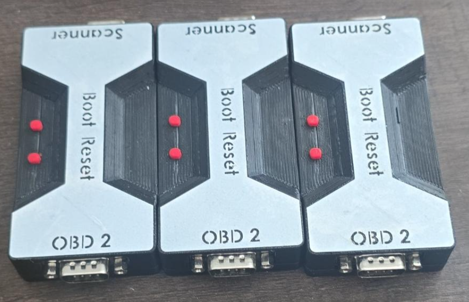
Completed CAN Bus Module hardware
Back to Projects

Project Summary

The CAN Bus Module project focused on developing a compact embedded electronics module for communicating with Controller Area Network systems used in robotics, automation equipment, and mobile machinery. The module was designed to support reliable data exchange between sensors, controllers, actuators, and diagnostic tools in distributed machine-control environments.

The project emphasized practical integration needs, including robust wiring, connector planning, embedded communication logic, diagnostic access, and compatibility with machine-level control architectures. The module provides a foundation for collecting system data, monitoring device status, and connecting subsystems across a shared communication bus. It is also programmable, allowing features to be added, removed, or adapted to meet the specific requirements of each project.
Images

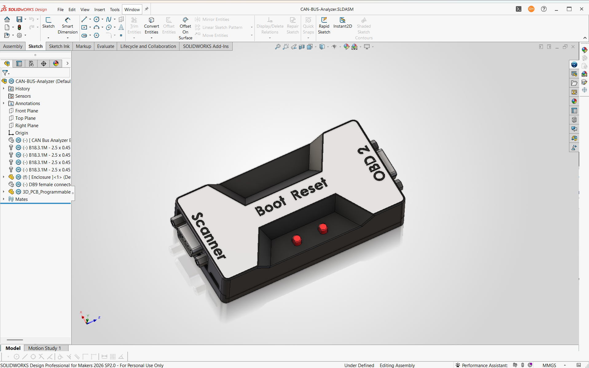
CAN Bus Module 3D model
3D model of the CAN Bus Module.
Using EasyEDA, I created the electrical schematic for the CAN Bus Module, organizing the microcontroller, CAN communication circuitry, power regulation, switches, and external connections into a complete system design. Developing the schematic helped define how each subsystem would interface before moving into PCB layout and hardware assembly.
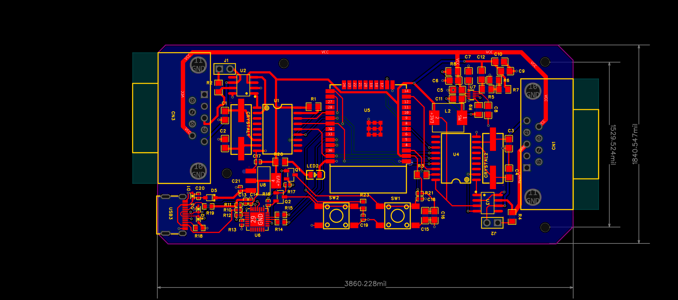
CAN Bus Module PCB layout
PCB layout for the CAN Bus Module.
I created this bill of materials in Airtable to organize the components required for the module assembly. The BOM was structured to track part information, quantities, and other relevant assembly details in a centralized format, making it easier to manage components and support the build process.
CAN Bus Module PCB view 3
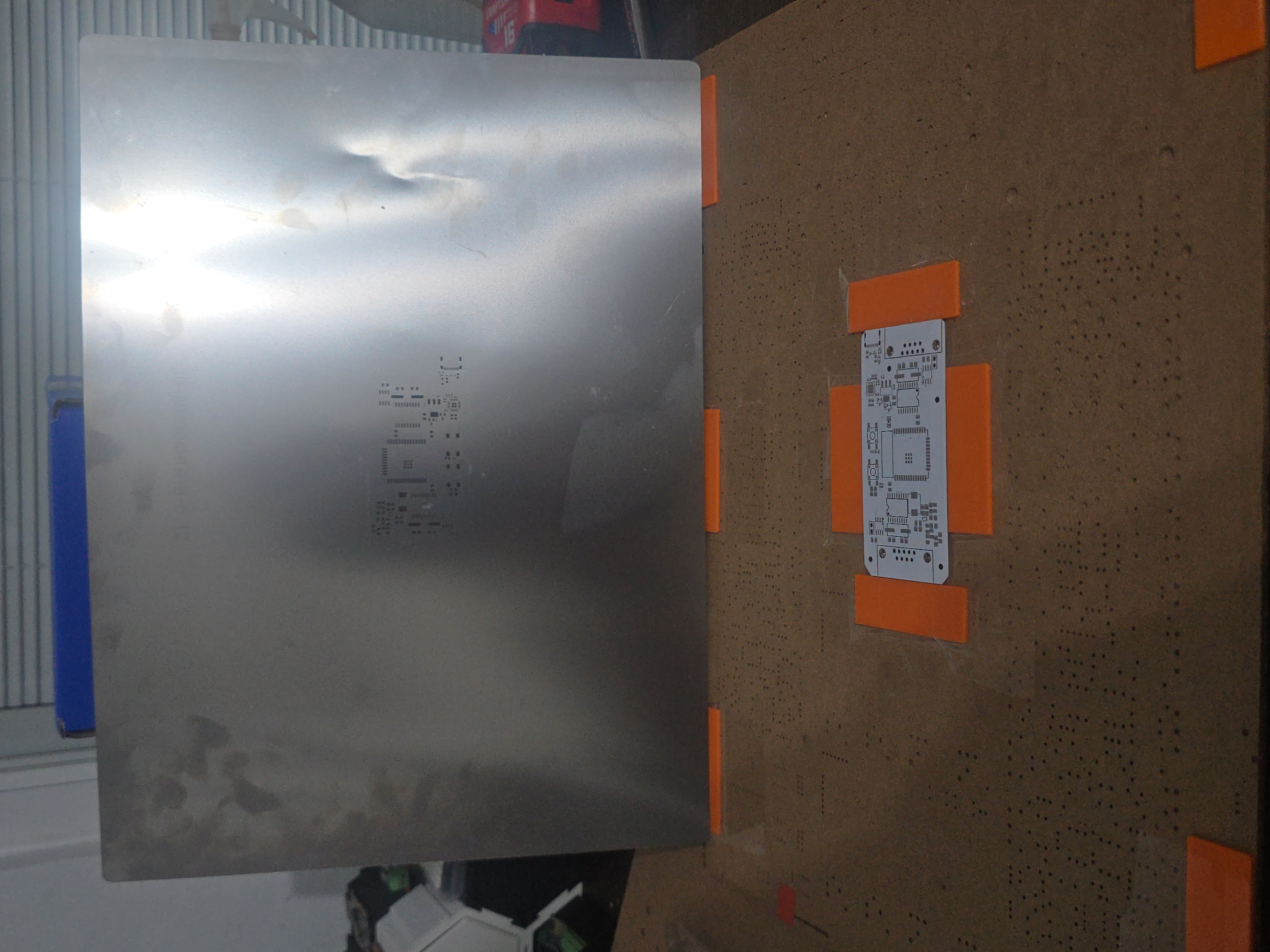
To prepare the CAN Bus Module PCB for component assembly, I positioned and secured the board beneath a PCB stencil used to apply solder paste. Careful alignment of the stencil ensured that solder paste was deposited accurately onto the surface-mount pads before component placement and reflow soldering.
CAN Bus Module PCB view 2
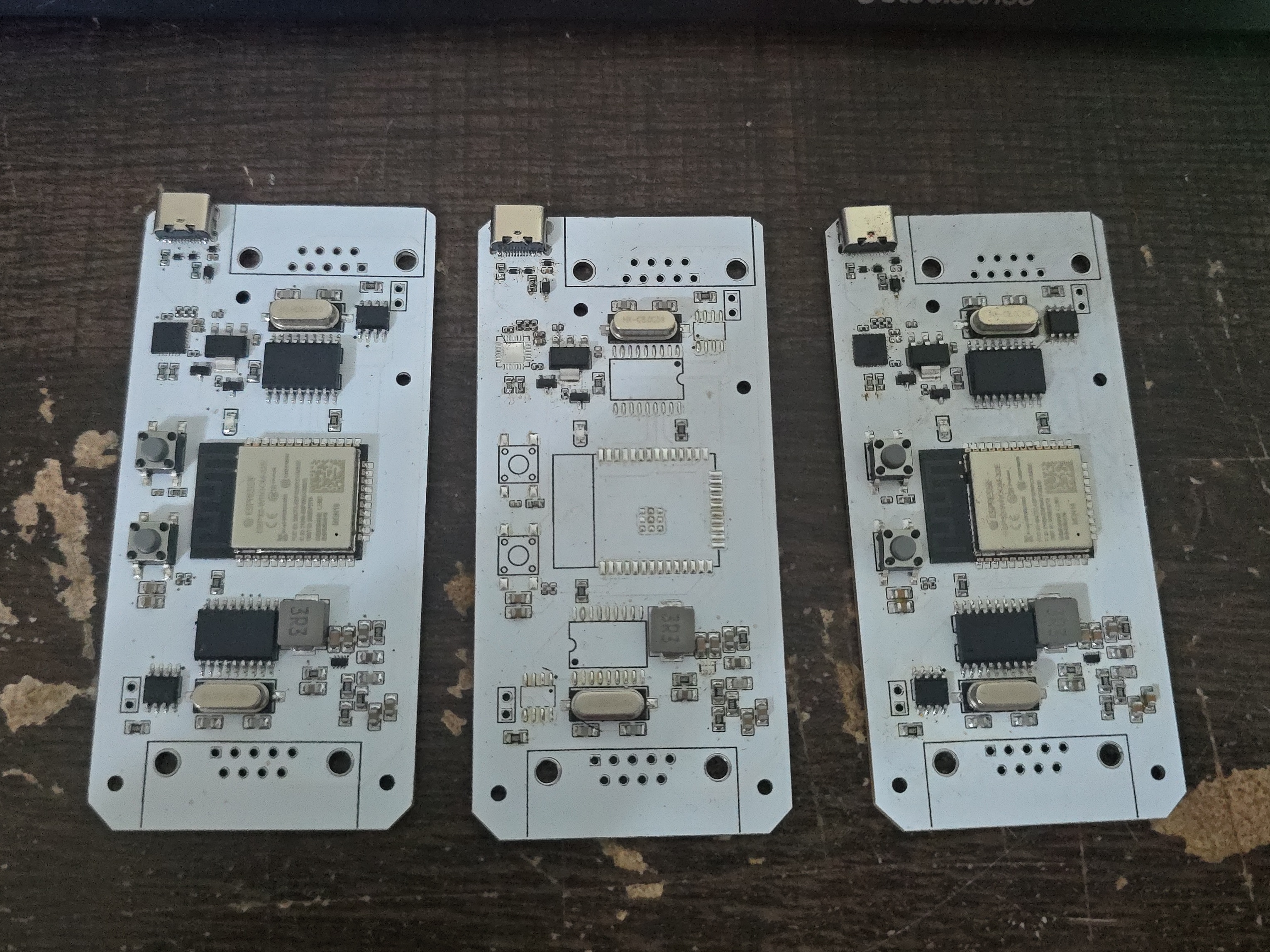
These CAN Bus Module PCBs are shown at different stages of assembly, with surface-mount components and communication hardware installed on the boards. Building multiple units allowed me to verify the assembly process, component placement, and repeatability of the design before moving on to electrical testing and programming.
CAN Bus Module build instructions
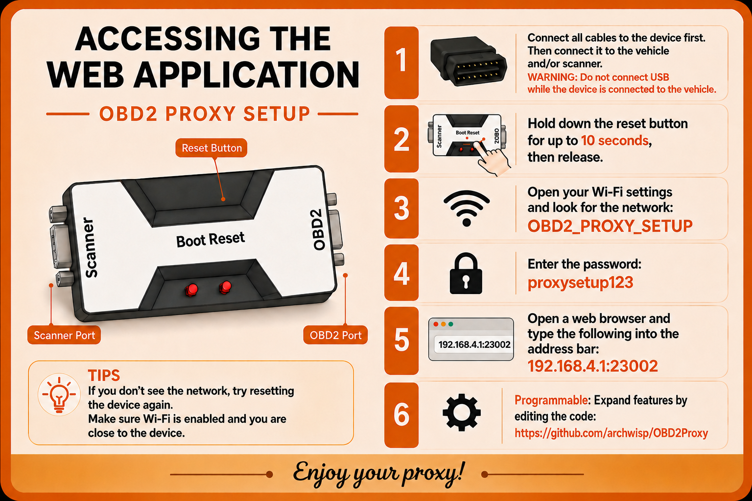
Assembly and setup instructions.
Completed CAN Bus Module hardware
Completed CAN Bus Module hardware.